How to Create the PWM signal?
One way to create the PWM signal is using a high speed comparator which compares a triangular signal of high frequency and audio input and generates a series of pulses so that the pulse width corresponds to the amplitude frequency audio signal. The comparator then uses a switch controller that simultaneously manages a high-power switch (usually consisting of MOSFETS), which generates a copy of high signal PWM comparator.
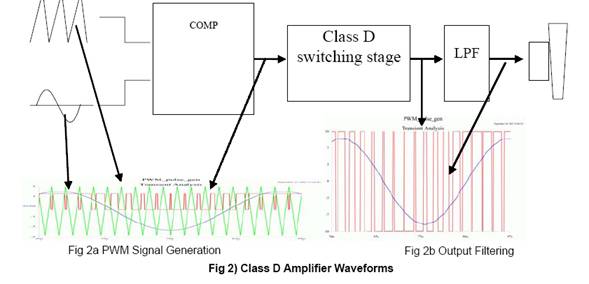
The PWM output is connected to a low pass filter that removes high frequency components of the PWM signal to retrieve the information and send an audio signal to the speakers. A switching frequency high enough needs to be able to obtain a reasonable frequency answer and minimal distortion. Most of the class D amplifiers use switching frequencies above 20 KHz so that the switching is inaudible so use most often between 50 kHz and 1 MHz to ensure that condition (standard frequency switching of a class D amplifier that audio = 100KHz). These high frequencies require that most components of the amplifier are capable of working at high speed. We must also say that for inverters using frequencies between 5 and 20 kHz and choppers use frequencies of 10 kHz (in both cases, switching is not inaudible).